Standard network structure
To keep the configuration of simple network structures to a minimum, the CANopen standard supports default settings for message IDs (‘Predefined Connection Set’). A simple network structure features 1:n communication between a control device (Master) and a number of lower-order devices (Slaves). This set of standard default settings supports one emergency message per node, synchronisation and timestamp messages, one SDO connection per device, the NMT messages for node control and monitoring, and up to 4 transmit and 4 receive PDOs per device.
In a CANopen network, it is possible to define up to 127 nodes. These nodes share the 11-bit identifier space. A distinction is first made between network-related and device-related functions. A CAN-ID is reserved for each of the network-related functions (e.g. NMT node control). A further CAN identifier is required per CANopen device for device-related functionality (e.g. emergency calls or PDOs). After all, it must be possible to distinguish between the same functions for different CANopen devices. The key functions are assigned a higher-priority COB-ID. For future extensions, and for historical reasons, some message IDs have not been assigned. It is therefore possible to create systems with a higher-order node and up to 127 slave nodes without any configuration.
CAN identifier allocation
The following diagram shows the final standard allocation of the CAN identifier space within a standard CANopen configuration:
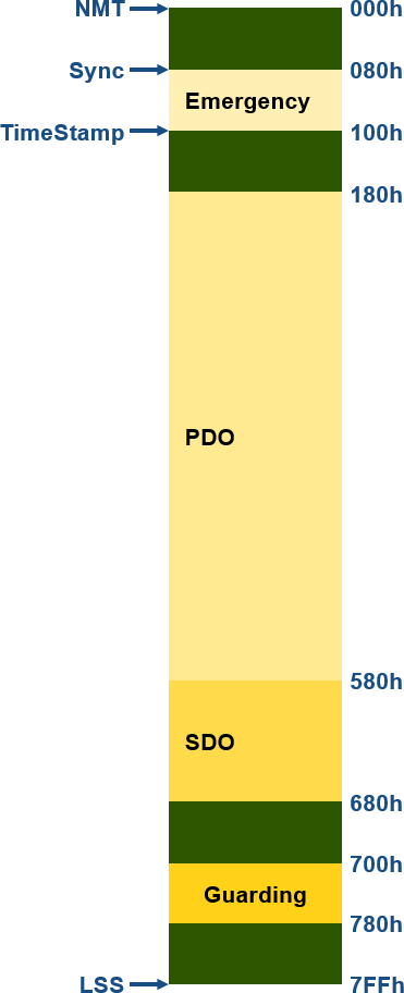

The following table shows the allocation of identifiers according to these standard preferred settings (“Predefined Connection Set”):
| Communication object | COB-ID(s) hex | Slave nodes |
|---|---|---|
| NMT node control | 0 | Receive only |
| Sync | 80 | Receive only |
| Emergency | 080 + NodeID | Transmit |
| TimeStamp | 100 | Receive only |
| PDO | 180 + NodeID 200 + NodeID 280 + NodeID 300 + NodeID 380 + NodeID 400 + NodeID 480 + NodeID 500 + NodeID |
1. Transmit PDO 1. Receive PDO 2. Transmit PDO 2. Receive PDO 3. Transmit PDO 3. Receive PDO 4. Transmit PDO 4. Receive PDO |
| SDO | 580 + NodeID 600 + NodeID |
Transmit Receive |
| NMT node monitoring (node guarding or heartbeat) | 700 + NodeID | Transmit |
| LSS | 7E4 7E5 |
Transmit Receive |
SDOs and PDOs are always defined in pairs – that is, for transmission and reception. The rule is that the CANopen node transmits on the lower (and therefore higher priority) COB-ID and receives on the higher (and therefore lower priority) COB-ID.
Example
As an example, consider the communication between a higher-level control device (master) and a CANopen node with ID 5 (slave). The master uses PDOs with COB-IDs 0x205, 0x305, 0x405 and 0x505 to transmit process data. It receives such data from this node via the PDOs with COB-IDs 0x185, 0x285, 0x385 and 0x485. A control device can therefore exchange a maximum of 32 bytes of process output data and 32 bytes of process input data with a standard slave node. In our example, the central control device accesses the Object Directory of CANopen node 5 via an SDO request with COB-ID 0x605 and receives the corresponding SDO response via COB-ID 0x585.
Complex network structures
To set up complex CANopen network structures – for example, a structure with more communication links or with (many) more PODs per device than the standard 4 – the predefined identifier allocation must be changed via the identifier allocation configuration. Identifiers from node IDs that are not used in the system can be utilised for this purpose. The use of a configuration tool is recommended for this.