Broadcasting
The primary function of a CANopen system is, of course, the exchange of process data. Not only are most of the CAN-IDs reserved for this purpose, but also the majority of the Object Directory. The transmission of process data takes place without any additional protocol overhead and follows the so-called “producer/consumer principle”. This means that a message sent by a CAN node – the “producer” – can be received by all other CAN nodes, the “consumers”. This principle is referred to as “broadcasting” and is a highly effective method of data transmission.
Process Data Object (PDO)
A CANopen message containing process data is called a “Process Data Object” (PDO). As already described, the transmission of PDOs is only possible in the “Operational” status. PDOs do not have a fixed format. The data field of a PDO can be between one and eight data bytes in size.
Nor can the contents of a PDO be easily interpreted without further information. The basic principle is that both the sender and the receiver know how the contents of a PDO are defined. It is therefore sufficient to identify the PDO solely by its COB-ID, the CANopen term for the CAN Object Identifier. The so-called ‘PDO mapping’ describes which individual process variables are included in a PDO’s data field, how they are arranged, and their data type and length. To this end, the content and meaning of each data field in every defined PDO are described in the form of a PDO mapping record in the Object Directory of both the CANopen transmitter and all desired receiver(s).
The PDO producer compiles the data field of a PDO in accordance with the corresponding TxPDO-mapping. To do this, it copies the current data of the variables from the Object Directory and pastes it into the data field of the PDO before the CAN message (PDO) is transmitted. The same process occurs on the consumer side: based on the RxPDO mapping record, the data bytes from the received PDOs are copied to the correct (sub)indices in the local Object Directory.
The device application software will then use this information to initiate device-specific actions. For example, switching digital outputs. A CANopen node that wishes to receive a particular PDO simply needs to activate the reception of the corresponding CAN message. This is done using “set valid” for the relevant COB-ID item in the OD.
But back to PDO mapping. The principle behind the mapping of process variables is explained in the following figure. The variables take the form of Object Directory items in the application profile. The mapping of the individual CANopen process variables within the data field of a PDO is described in tabular form. This is also provided as an Object Directory item, specifically for each transmit and receive PDO in Indexes [16xx] or [1Axx]. These tables, and the mapping of the process variables within the data field of a PDO, can be configured via SDO write access. This is normally carried out by the Master during initialisation.
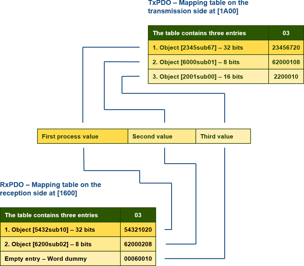
In this example, there are exactly two objects on the left: from object (process variable) [2345sub67] from the PDO producer to object [5432sub10] of the PDO consumer, and from object [6000sub01] of the producer to object [6200sub02] of the consumer. The third sending object [2001sub00] is not defined on the receiving end and is therefore covered by a so-called dummy object. The mapping tables are of the “PDO Mapping” type and contain, in sub-index 0, the number of assigned objects and, in sub-indices 1 to 8, the mapping Object Directory items themselves as DWORDs. This contains the 24-bit OD address (index, sub-index) and the 8-bit encoded length of the OD item. A CANopen device that supports 8 mappings has a sensitivity of 8 and can perform byte-by-byte mapping. CANopen devices with a sensitivity of 1, on the other hand, support mapping of each PDO bit (‘bit-mapping’). In that case, there are 64 entries in the mapping table.
Communication parameters (PDO)
However, a PDO is not only defined by the mapping but also by the CANopen communication parameters. These are: COB-ID, i.e. the CAN-ID, “transmission type” and “inhibit time”, all of which can be configured via corresponding Object Directory items. The location of this additional Object Directory item has an offset of 0x200 before the original mapping item, i.e. for transmit PDOs [18xx] and for receive PDOs [14xx]. Each PDO is therefore described by two different OD items, which are closely linked. Both are configured by the system integrator. The following table shows the “PDO parameter” record:
| Sub-Index | Content | Data type |
|---|---|---|
| 0 | Highest supported sub-index | BYTE |
| 1 | COB-ID | DWORD |
| 2 | Type | BYTE |
| 3 | Inhibit time in ms | WORD |
| 5 | Event timer | WORD |
Subindex 1 contains the PDO’s CAN identifier as a DWORD. The MSB bit indicates whether the PDO is active (valid) or inactive (invalid). A set MSB (invalid) means a value of 0x80000199, for example, describes an invalid first TxPDO of node number 25. The transmission type of a PDO can be set via the second sub-index. It is necessary to first distinguish between synchronous and asynchronous PDOs:
| Value[Dec] | Type |
|---|---|
| 0 | Acyclic synchronous |
| 1...240 | Cyclic synchronous |
| 241...251 | Reserved |
| 252 | Synchronous, RTR only |
| 253 | Asynchronous, RTR only |
| 254...255 | Asynchronous |

Asynchronous PDOs
Asynchronous PDOs are event-driven and represent the standard transmission type of PDOs. This means that whenever at least one of the process variables defined in the PDO is changed (for example, a change in an input value), the PDO is transmitted immediately. For these, the values 255 or 254 must be entered as the PDO type.
Synchronous PDOs
Synchronous PDOs are only transmitted following the prior receipt of a synchronisation message (Sync Object). The PDO data transfer is thus carried out synchronously across the entire network, more or less simultaneously. However, it is far more important that all inputs must be sampled upon receipt of the Sync Object, so that a uniform snapshot of the process data is created. With the next synchronisation message, the recorded data is then transmitted in the synchronous PDOs. Consequently, there is a delay corresponding to the cycle time of the synchronisation message, as the consumer receives the process variables at the time of the previous Sync message. In the output direction, too, the data in the received synchronous PDOs only become valid upon receipt of the next synchronisation message. In this way, input and output data remain roughly in step.
Sync interval
To prevent the bus from being blocked by a large number of synchronous PDOs, which are transmitted following each Sync message, the values 1 to 240 of the synchronous PDO type act as cyclic counters for the transmission interval. For example, [18xxsub02] = 4 means that the synchronous PDO is only transmitted after every fourth Sync message. Irrespective of this, the device must always sample inputs with every Sync message, as it may happen that synchronously recorded process variables in a PDO are requested by RTR. In this case, the CANopen device must immediately transmit the corresponding PDO, containing synchronously recorded values. In [1006], the parameter “Communication Cycle Period”, the Sync interval for nodes can be set in microseconds.
Delay
Finally, in sub-index 3, an “inhibit time” can be set for asynchronous PDOs. The value must be a multiple of 100 microseconds. This delay (inhibit) is useful if frequent uncontrolled changes to a CANopen device’s input values occur, for example, with an open analogue input. If the inhibit time is configured, the node will not resend the relevant PDO during this period, thereby ensuring that no unacceptable CAN bus load is caused by a so-called ‘chattering’ input. The inhibit time is, of course, only used for TxPDOs. It has no significance for RxPDOs.
Cyclical transmission
Asynchronous TxPDOs can be transmitted cyclically using the event timer, sub-index 5. If the value is greater than 0, it becomes a timer in milliseconds. Once this has elapsed, the PDO is transmitted. Transmission therefore takes place both when a CANopen device input changes and when the timer has elapsed. This sub-index is also only relevant for transmit PDOs.
CANopen resources
A CANopen node usually has four transmit PDOs and four receive PDOs, with a COB-ID reserved for each PDO. This therefore takes up a total of 127 * 4 * 2 = 938 COB-IDs, which is almost half of the total identification space. However, as a result of so-called ‘Object Linking’ – that is, the establishment of communication between a transmit PDO and a receive PDO – COB-IDs are released. After all, by linking the producer to the consumer(s), the COB-ID must be adapted to that of the communication partner, thereby freeing up a previously reserved COB-ID. Consequently, in practice, for a network with 127 network nodes, an average of eight COB-IDs are available per device for TxPDOs. For networks with fewer nodes, the unused COB-IDs can of course also be utilised. The system integrator must always maintain an overview of the allocation of the identifier space and the COB-IDs in use. For more complex systems, a software tool – such as CANopen ConfigStudio – is recommended. This tool, for example, automatically handles PDO mapping and linking.