From digital to bus
A CAN controller is a fully digital solution and is usually part of a microcontroller. It transmits, via the so-called TxD output, and receives, via the RxD input, digital signals that are only suitable for communication on the printed circuit board. Electronics – known as the physical layer – are therefore required to transmit these signals reliably, without interference and over long distances. At the same time, the TxD output and RxD output must be connected in such a way that the RxD can read back the TxD signal to recognise dominant bits.
The CAN protocol itself does not define such a physical layer, and consequently there are a range of different electronic solutions for various applications. For example, EVC test facilities and potentially explosive atmospheres utilise fibre-optic-based CAN buses. In ground-to-ground environments with longer distances, such as on ships, current-controlled interfaces that operate on the basis of pulses are used. In older solutions, (modified) RS485 is frequently used. CAN controllers therefore often include the option to programme the output and input for the relevant control of physical layers.
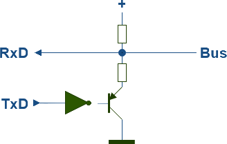
The vast majority of physical layers operate on the principle of a bus in the form of a wire connected to the power supply via a resistor, and open-collector TxD’s. If the TxD output sends a ‘1’, nothing happens and the resistor keeps the bus high. If a TxD output sends a ‘0’, the inverter and the transistor will pull the bus down to earth. Consequently, ‘1’s are recessive and ‘0’s are dominant.
Twisted pair
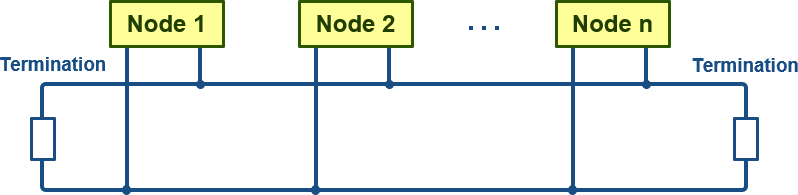
The automotive industry has developed a physical layer that operates on the basis of a twisted pair and possesses very good electrical properties. This has been formalised as the ISO 11898-2 standard and is used in virtually all standard, automotive and industrial applications. The topology is a line (bus). To prevent signal reflections, both ends of the network must be terminated with 120Ω resistors. Furthermore, the lengths of the branch lines connecting the individual nodes must be kept as short as possible. At 1 Mb/sec, the branch lines must not exceed 30 cm.
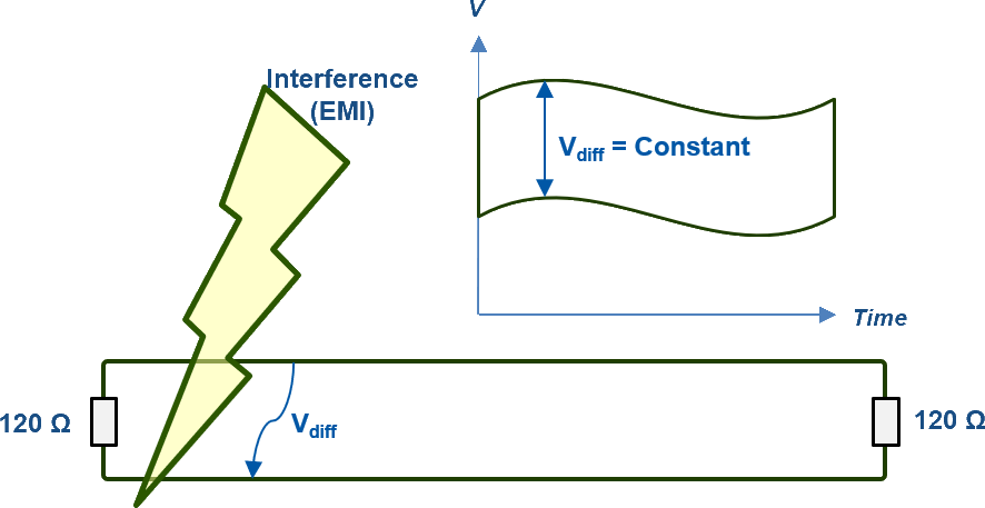
Thanks to the twisted pair, the bus is highly resistant to external interference, even when this occurs only locally. Both bus lines carry the same signal, but in inverted form. By subtracting the two signals (negative minus positive) from one another at the physical layer, a signal with double the amplitude is created, whilst at the same time any potential signal interference is subtracted and thus compensated for.


Physical layer ISO-11898-2
The standard physical layer is known as ISO 11989-2. In the case of CiA®, this is DS 102, also known as CAN High-speed. In the case of CiA® DS 102, the connector – including Sub-D9, RJ45 and M12 – and pinout are also standardised. This layer also features a range of safeguards to prevent interference and even damage to the bus. The key parameters are listed below:
| Parameter | Min | max | |
| DC Voltage on CANH and CANL | -3 | 32 | V |
| Transient voltage on CANH and CANL | -150 | 100 | V |
| Common Mode Bus Voltage | -2.0 | +7.0 | V |
| Recessive Output Bus Voltage | +2.0 | +3.0 | V |
| Recessive Differential Output Voltage | -500 | 50 | mV |
| Differential Internal Resistance | 10 | 100 | kΩ |
| Common Mode Input Resistance | 5.0 | 50 | kΩ |
| Differential Dominant Output Voltage | +1.5 | +3.0 | V |
| Dominant Output Voltage (CANH) | +2.75 | +4.50 | V |
| Dominant Output Voltage (CANL) | +0.50 | +2.25 | V |
| ESD | 2 | kV |
The signals on the bus look as follows:
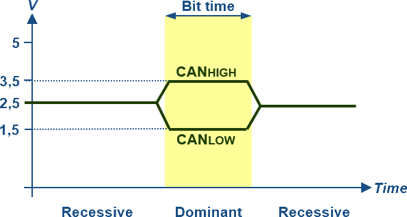
The nominal propagation delay of twisted pair may be 5 ns/m. This results in a bus speed of 1 Mbit/s for a bus length of 40 m. The overall structure of the physical layer therefore becomes quite complex. Fortunately, all well-known semiconductor manufacturers supply chips with a fully integrated ISO-11898-2 interface that are both inexpensive and readily available.
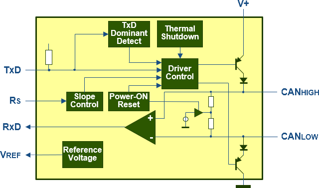
Often, though not always, these chips include additional features such as adjustable edge steepness, to optimise the signals on the bus (Rs in the diagram above), or thermal protection. Also bear in mind the fan-out when setting up a network with many nodes. Some versions have a fan-out capable of driving up to 110 nodes, whilst other chips are limited to 32 nodes.
Galvanically isolated
The standard physical layer does not provide galvanic isolation. The basic principle behind CAN is that high-volume products are developed on a cost-effective basis: fully developing and optimising the physical layer is therefore significantly cheaper than implementing galvanic isolation. In industrial automation and the system integration of CANopen components, the situation is, of course, quite different. The savings made by not using galvanic isolation do not outweigh the costs of troubleshooting and replacing a component. At the same time, all manner of undesirable effects can occur in industrial environments due to earth faults and the like. In CAN systems, galvanic isolation is generally achieved by optically decoupling the TxD and RxD signals from the microcontroller to the physical layer and by galvanically isolating the power supply to the physical layer. There are now also physical layer chips on the market that have galvanic isolation integrated on board.