Bit timing
The bus speed depends on the bus timing, which is derived from the system clock speed in the CAN controller. Using a ‘baud rate prescaler’, this system clock speed is reduced to a basic CAN clock speed, also known as Time Quantum. This is not yet the CAN bus speed, as in CAN, the timing of a bit is built up on this basis:
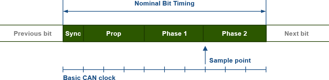
- SYNC_SEG is 1 time quantum long. It is used to synchronise the various nodes. CAN logic is synchronised on the bit edges;
- PROP_SEG is programmable from 1 to 8 time quanta. It is used to compensate for signal delay across the network;
- PHASE_SEG1 is programmable to a length of 1–8 time quanta. It is used to compensate for rising and falling edge errors and can be dynamically extended during synchronisation. This dynamic synchronisation can be set between 1 and 4 time quanta. This is referred to as Synchronisation Jump Width (SJW);
- PHASE_SEG2 is also programmable to a value of 1–8 time quanta. It is also used to compensate for rising and falling edge errors and can, conversely, be dynamically shortened during synchronisation (negative SJW).
- At the sample point, 3 samples are taken (half a time quantum distance), with the majority determining the value;
- The total bit timing may range from 8 to 25 time quanta.
These values allow the exact sample point to be determined with precision: a late sample point allows for a maximum bus length, whilst an early sample point allows for slower rising and falling bit edges and, consequently, less radiation and interference. Generally speaking, the best bus timing is one that contains as much Time Quatum as possible and where the sample point lies at approximately 80 per cent of the total bit time. The final desired bus timing is programmed into the standard Timing Registers 0 and 1 of the CAN controller.
Bit stuffing
The CAN bit stream is encoded using the Non-Return-to-Zero (NRZ) method. This means that during a bit time, a bit remains constantly dominant (‘0’) or recessive (‘1’) and therefore does not change. However, the CAN logic uses edges to synchronise the data stream; see the bit structure above. It is essential that there are sufficient edges in the stream. For this reason, after five consecutive identical ‘0’s or ‘1’s, the CAN controller will automatically add a bit of the opposite state to the data stream. The receiving CAN controllers are aware of this and will therefore remove the next bit from the stream after five identical bits. This mechanism is known as bit stuffing. The user is not aware of this, but bit stuffing does have a (very limited) effect on the data rate.


Bus length
With traditional serial connections, the length of the bus is not particularly important: whatever is transmitted at one end will (sooner or later) arrive at the other end. However, the principle of per-bit arbitration, which is used by CAN, requires a comparison between the local bit levels of all nodes that have been distributed across the bus per bit within a specific time interval. The acknowledge works in the same way. This means that a CAN bit and the response from the nodes must be transmitted back and forth within one bit time.
The signal distribution requirement on the bus depends on the signal propagation time. This is approximately 5 ns/m, and in principle it makes no difference whether the medium – the bus – is copper or fibre optic. Consequently, the required duration of a bit interval is extended in line with the increase in the length of the bus. After all, another node must respond within the bit time during arbitration and later during the acknowledge. This limits the length of the bus, and this limitation depends on the selected speed. After all, a higher speed shortens the bit time.
It is not only the bus itself that determines the total delay. The electronics between a CAN controller and the copper or fibre-optic cable – the physical layer – also cause delay. The graph below is based on the standard physical layer used by most nodes.
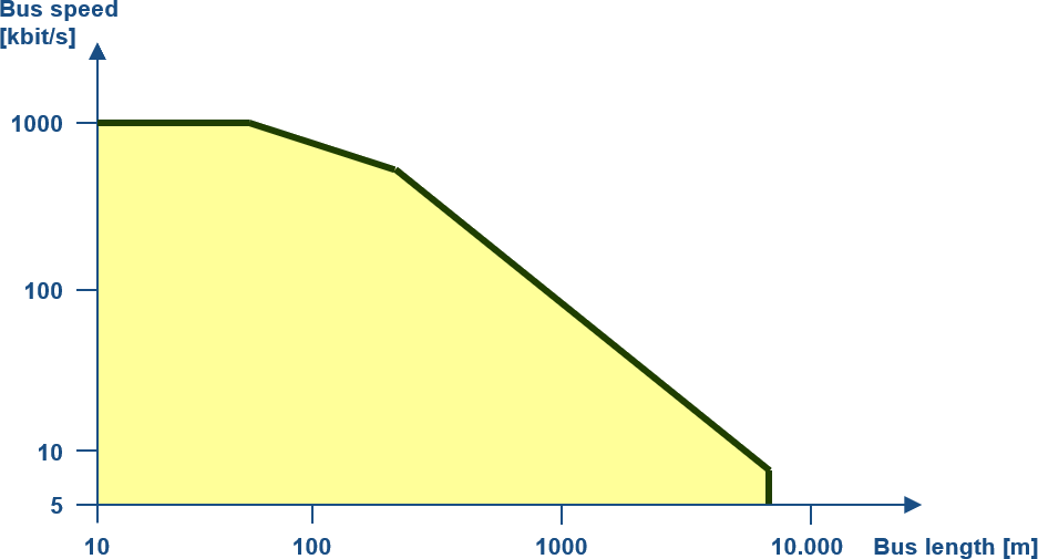
The maximum bus length and the maximum bit rate are therefore inversely proportional. Bear in mind that (non-standard) physical layers, repeaters and the like can sometimes significantly increase the total delay time, thereby further limiting the maximum bus length.
Standard bus timing and length
It will be clear that determining the correct bit timing can be quite a challenge. For specialists, this makes it possible to establish reliable CAN communication even in challenging environments. However, this is not necessary for the general user. Based on standard physical layers and standard bus lengths, CiA® (CAN in Automation) has defined standard bus speeds and corresponding bus timing. These are supported by virtually all CAN equipment.
| Baudrate | Maximum buslength | BTR0 | BTR1 |
|---|---|---|---|
| BTR0/1 = Bus timing register values for the NXP 82C200 @16 MHz. Many CAN controllers use the same timing as this chip, but there are also exceptions. | |||
| 1000 kBit/s | 25 m | 00h | 14h |
| 800 kBit/s | 50 m | 00h | 16h |
| 500 kBit/s | 100 m | 00h | 1Ch |
| 250 kBit/s | 250 m | 01h | 1Ch |
| 125 kBit/s | 500 m | 03h | 1Ch |
| Reserved | |||
| 50 kBit/s | 1000 m | 09h | 1Ch |
| 20 kBit/s | 2500 m | 18h | 1Ch |
| 10 kBit/s | 5000 m | 31h | 1Ch |
In the vast majority of cases, these values will work perfectly well. However, with maximum bus lengths, buses with extensive branching, or the use of one or more repeaters, these values may not be sufficient.
Autobaud
Manufacturers often state that CAN equipment has an Autobaud function. To put it plainly: CAN controllers do not have an Autobaud function.
What manufacturers mean by this term is that software is used to set the CAN controller’s timing to the standard CiA® values mentioned above. As soon as actual communication takes place at a particular value, the correct bus speed has been found. This ‘autobaud’ software works reasonably well in practice, but is certainly not entirely fault-free.