At its core, CANopen enables the transmission of time-critical process data according to the producer/consumer principle, offering the following services:
- A standardised description of connected devices (data, parameters, functions, programmes) in the form of the so-called “Object Dictionary”.
- Access to all objects of a device via a standardised transmission protocol based on the client/server principle.
- Standardised tools for device monitoring (node monitoring/heartbeat), fault signalling (including emergency calls), and network coordination (network management).
- Standardised system tools for synchronisation (synchronisation messages) and central timestamping.
- Standardised support functions for configuration, baud rate and device identification via the bus.
- Standardised allocation mechanism for message IDs to facilitate system configuration in the form of a so-called “Predefined Connection Set”.
Specifications
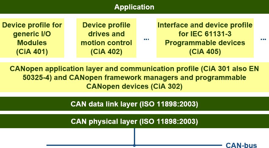
The CiA 301 standard ‘CANopen Application Layer and Communication Profile’ describes the CANopen base specification and is available from the CAN user group ‘CAN-in-Automation e.V.’ (CiA) in Germany. The extended communication mechanism is described in CiA 302: “Framework for Programmable Devices”, and is primarily aimed at communication with PLCs, HMIs and CANopen tools. The specifications CiA 303, CiA 305 and CiA 306 define standards and recommendations for cables, connector connections, SI units, layer setting services (LSS) and the Electronic Data Sheet (EDS) specification. All CANopen specifications have been developed by companies that are members of the CIA and are freely available. An overview of CANopen devices and application profiles can be found in the Device and Application Profiles section.


Physical structure of a CANopen network
Bear in mind that CANopen is a standard that utilises CAN and essentially consists solely of software. It therefore does not alter the CAN standard. When we refer in this context to direct addressing using Node IDs, this is merely a software convention. In reality, every participating CAN controller will receive such a message, but it is the software that determines whether a response is sent.
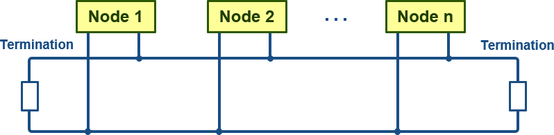
The underlying CAN architecture defines the physical structure of the CANopen network. For this reason, a line (bus) topology is used. To prevent signal reflections, both ends of the network must be terminated with resistors. Furthermore, the maximum permissible branch lengths for connecting the individual network nodes must be observed.
The recommended permissible bit rates for a CANopen network are defined in CiA 301: 10, 20, 50, 125, 250, 500, 800 and 1000 Kb/sec. CiA 301 also sets out a recommendation for the configuration of the bit timing.
Furthermore, for CANopen, two additional conditions must be met within a network:
- All nodes must be configured to the same bit rate, and
- Node IDs must be unique and must therefore not occur more than once.
Unfortunately, there are no mechanisms in place to ensure these conditions are met automatically. The system integrator must check the bit rate and node ID of each node whilst wiring a network and adjust them if necessary.
Normally, the node ID is configured directly on the device via DIP switches or hexadecimal rotary switches. Alternative solutions require these parameters to be set via software using two reserved CAN IDs, with the aid of the so-called ‘LSS service’ (layer setting service), as described in CiA 305.
Some nodes feature automatic baud rate detection. However, such (hardware-based) detection is not possible within CAN. What these nodes do is simply try out all possible standard CiA baud rates until communication actually takes place.