CAN XL Bus Transceiver
One of CAN XL’s key strengths is its ability to reuse the existing physical infrastructure. Like its predecessors, it is based on a two-wire bus with twisted pairs and a 120-ohm terminator. This means that, in many cases, the existing cabling can be retained, which simplifies migration.
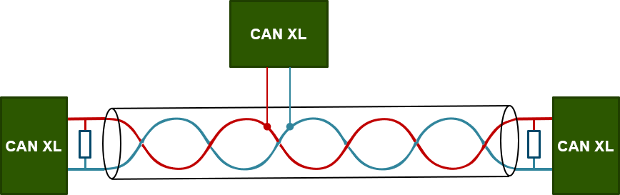
With the introduction of CAN FD, a new physical layer – the driver electronics for the bus – was developed to cope with the higher speeds. These are called CAN SIC – an abbreviation for Signal Improvement Capability –. To achieve higher data rates of over 8 Mbit/s, CAN XL introduces the concept of mode switching in combination with new SIC XL transceivers.
- The SIC mode is used in the arbitration phase of the CAN XL protocol. It is also possible to use this mode in the data phase. In this mode, the CAN SIC XL transceiver functions as a standard CAN SIC transceiver. With this mode, speeds of up to 8 Mbit/s are possible in the data phase.
- In FAST mode, the transceiver regulates both levels on the network lines, just like a FlexRay transceiver. The symmetrical, alternating differential bus signal and the 100-ohm transmitter impedance – similar to a typical CAN wire impedance – enable higher bit rates in the data phase of the CAN XL protocol


Mode Switching
To achieve higher data rates of over 8 Mbit/s, CAN XL introduces the concept of mode switching in combination with new SIC XL transceivers. During the arbitration phase, communication still follows the conventional scheme, but for the data phase, the system can switch to a high-speed push-pull mode with a reduced signal amplitude. This enables bit rates of up to 20 Mbit/s, whilst maintaining the reliability of the CAN transmission principle. Although classic error frames are limited in this high-speed mode, reliability is ensured by the improved CRC mechanisms.
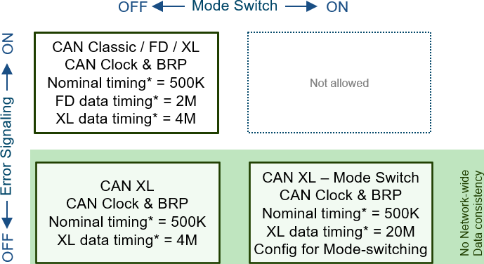
In CAN Classic, CAN FD and CAN XL (non-FAST), data consistency is guaranteed. As a result, either all nodes in a network receive a message correctly, or none of them do. Because classic error frames are limited in FAST mode, this mode does not guarantee data consistency across the entire network.
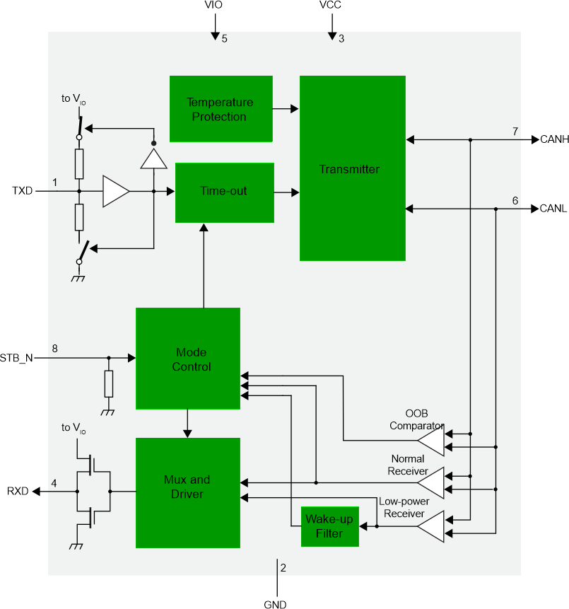
The switch from SIC mode to FAST mode is controlled by the CAN XL controller – often integrated into the microcontroller – via the TxD pin. During the arbitration phase, the TxD signals are the same as for all other types of transceivers. A high TxD signal provides the recessive level on the network lines, whilst a low TxD signal provides the dominant level. During the FAST mode phase, the CAN XL controller transmits PWM symbols to the transceiver.
CAN FD and CAN XL Mixed Mode
CAN now uses three different Physical Layers: HS (High Speed), introduced for CAN Classic; SIC for CAN FD; and SIC XL for CAN XL. These transceivers have different maximum speeds.
| CAN HS | CAN SIC | CAN SIC XL | |
|---|---|---|---|
| CAN Classic | Max 1 Mbit/s | Max 1 Mbit/s | Max 1 Mbit/s |
| CAN FD | Max 1 Mb/s | Max 8 Mb/s | Max 8 Mb/s |
| CAN XL | SIC-mode Max 8 Mb/s |
FAST-mode Max 20 Mb/s |
The dual use of CAN FD and CAN XL on a single bus has been described previously. However, CAN XL can only operate in FAST mode – i.e. at speeds of up to 20 Mb/s – if all transceivers are CAN SIC XL-compatible!
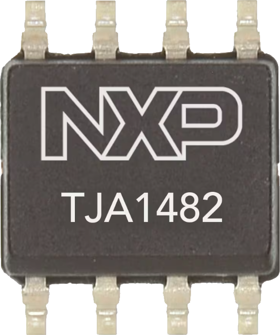
This means, therefore, that CAN FD nodes must also be equipped with a CAN SIC XL transceiver. As chip manufacturers have designed the building blocks for SIC and SIC XL to be pin-compatible, CAN FD nodes can therefore be easily upgraded.